![[Big Ear Masthead]](masthead.gif) Argus The Next Generation Radio Telescope STATUS REPORT ON ANTENNA DEVELOPMENT
Based on "Status Report On Antenna Development" By Brian Baertlein, Ohio State University ElectroScience Laboratory 9/13/99
The ElectroScience Laboratory (ESL) at The Ohio State University (OSU),
with the support of a grant from the SETI Institute, has been conducting
research on the design, construction and testing of antenna arrays for the
Argus radio telescope system.
The goal of this research is to construct an array with 64 elements to
operate over the wide frequency range of 400 - 2000 MHz (0.4 - 2.0 GHz).
The array should have: (1) a highly uniform pattern over a hemisphere with
low sensitivity both on the horizon and in the backward direction; (2)
low-loss components; (3) good matching to the receiver; and (4)
fabrication that is both inexpensive and easily done.
In a previous effort ESL used an antenna array comprised of closely-spaced
bent dipoles arrayed over a conducting flat surface (ground plane). Since
the elements were very close together, each dipole was significantly
influenced by nearby elements (i.e., mutual coupling). Measurements on an
array designed to operate around 1500 MHz showed some promise, but the
behavior varied too rapidly with frequency and the array did not operate
well over a wide frequency band. Hence, an investigation of alternative
designs was begun.
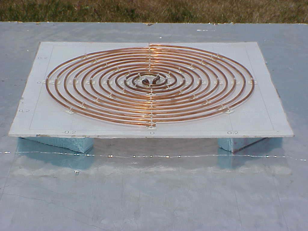
A planar two-arm Archimedean spiral over a conducting ground plane was
selected for study (see Figure 1 below). It is planar, meaning flat. It has
two interwoven spirals, creating a balanced structure. Each spiral is an
Archimedean spiral, meaning that the spiral expands outward linearly (at a
uniform rate) rather than exponentially (as in a logarithmic spiral). A
conducting ground plane is used to eliminate signals from being received in
the backward direction. The way the spirals are wound means that this
antenna receives radio waves having right circular polarization (winding
the other way would allow reception of left circularly polarized waves).
Although the goal was to achieve a frequency range (bandwidth) of 10:1, the
ground plane had the effect of reducing the bandwidth to only 5:1. However,
by simply increasing the diameter of the spiral to twice its previous size,
the 10:1 ratio can be achieved.
The prototype antenna shown in Figure 1 was designed for the frequency
range of 400 - 2000 MHz. It was constructed with 3/8" (outside diameter)
copper refrigeration tubing and has a diameter of roughly 60 cm (24"). The
tubing is held to a dielectric substrate with inexpensive tie-wrap mounts.
The antenna is placed about 5 cm (2") above a ground plane and is fed
through a wideband tapered coaxial balun (i.e., balanced-to-unbalanced
transformer). The total cost of the antenna components is about $30. GPS
satellites were used to check the antenna pattern at 1575 MHz, and it was
found to be close to uniform over much of the hemisphere. There was also
good matching to the receiver over most of the 5:1 bandwidth, although with
some need for improvement from 1700 - 2000 MHz. An alternative design for
connecting a coaxial cable to the antenna, based on surface-mounted
wideband transformers, has been developed and is now being fabricated. The
cost of the components, circuit card, and connectors is estimated to be
less than $10/antenna..
Although these antenna elements have been developed with a flexible array
geometry in mind, there are plans to develop some useful array
configurations and to verify the performance in such configurations. ESL is
currently exploring dense array concepts, in which smaller replicas of the
spiral are packed in voids between larger spirals.
HOME |
FEEDBACK |