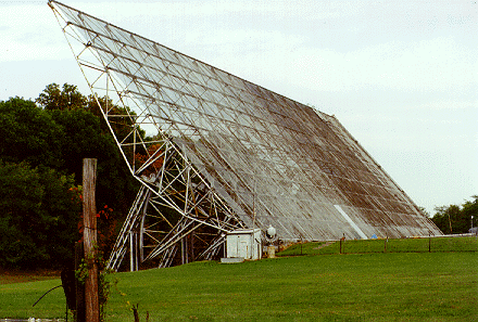
The Big Ear radio telescope had two large reflectors: to the north was
a flat reflector and to the south was a paraboloidal (curved) reflector
(look for a hot spot on the photo for this reflector).
The word "mirror" is sometimes used in place of the word "reflector".
In many optical telescopes, one or more mirrors reflect the light to
a focal point. A concave type of curved mirror will focus the light to
a point or to a focal region. A flat mirror will reflect the light to
a different direction without focussing. Similarly, radio waves (energy)
can be focussed by a concave type of curved metallic structure (reflector
or mirror), while a flat metallic structure (reflector or mirror) will
send the radio waves (energy) to a different direction without focussing.
 The photo at the left shows the flat reflector
plus the control house and the searchlight.
 |
 The photo at the left shows the wire mesh on the
flat reflector, plus a portion of the ground plane (with weeds penetrating the aluminum ground plane and climbing the flat reflector).
 |
 The photo at the left shows the flat reflector
plus the control house and the searchlight.
 The photo at the left shows the wire mesh on the
flat reflector, plus a portion of the ground plane (with weeds penetrating the aluminum ground plane and climbing the flat reflector).