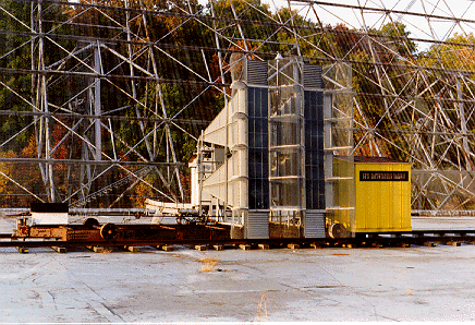
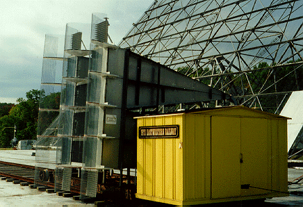
Shown here are two feed horns in close proximity to each other (best seen in the second photo). The horns
were designed for observing at frequencies around 1420 MHz (a wavelength
of about 21 centimeters = 0.21 meters = 8 inches). They were mounted
above the ground plane at the same height. Because of being located
above the ground plane, the declination of radio sources received was
almost exactly one degree higher than the nominal declination to which
the telescope was set. Setting the telescope declination was done from
the control house (find the hot spot for the
control house; this may be a challenge!).
The horns acted as funnels to the radio waves reflected off the
paraboloidal reflector (find the hot spot for
the paraboloidal reflector). After traveling to the end of each horn,
a metallic probe in the waveguide at the end of the horn acted as a
transducer and converted the energy of the radio wave photons into a
very small electrical current. For each horn, this current was
amplified many times by a low-noise sensitive preamplifier near the
probe. This amplified signal was carried by coaxial cable to the rest
of the receiver for more amplification and conversion into digital
signals. Except for the preamplifiers, the receiver along with the
computer and chart recorders was located in an underground room (called
the "focus room") below the horns.
The receiver was set up so that it switched between the two horns
several times each second (79 complete switching cycles per second), and the signal received in one horn (called
the negative horn) was subtracted from the signal received in the
other horn (called the positive horn). This difference signal was
then amplified more, detected (i.e., converted to a slowly-varying
direct current with the radio-frequency component removed), recorded
on a chart recorder, and converted into a digital signal for analysis
by and storage on a computer. This process of switching had the
advantages of: (1) allowing an area of the sky to be seen twice
within about 2.5 to 5 minutes of each other (depending on the
declination being observed), and (2) removing most of the undesirable
variation due to drifting of the receiver baseline and slow variations
of the sky background.
The movable horn cart was not built until the 1980s. It allowed
tracking a radio source for about 1 hour (+/- 30 minutes either side
of the focus). This tracking capability was found to be useful on
occasions while conducting the LOBES survey (LOw Budget Extraterrestrial
Survey) for narrowband signals (including those in our SETI = Search for
ExtraTerrestrial Intelligence).
 The photo at the left shows a medium-distance view of the dual feed horns looking north by northeast. The two horns are mounted on a movable cart which runs on an east-west track. The yellow "house" contains the drive motor and other components for moving the horns to allow tracking of a celestial radio source. [See the other photos below for better views of the tracking feed system.]
 The photo at the left shows a closer view of the dual feed horns looking northwest.
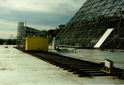
 The photo at the left shows a view of the dual feed horns looking west by northwest. The tracks along
which the cart moves run along an east-west line and are more visible in this photo.